|
|
Iptables |
|
| Home | Contents | Contact Us |
| Contents » TCP/IP repetition | Printer friendly version |
|
Permission is granted to copy, distribute and/or modify this document under the terms of the GNU Free Documentation License, Version 1.1; with the Invariant Sections being "Introduction" and all sub-sections, with the Front-Cover Texts being "Original Author: Oskar Andreasson", and with no Back-Cover Texts. A copy of the license is included in the section entitled "GNU Free Documentation License". All scripts in this tutorial are covered by the GNU General Public License. The scripts are free source; you can redistribute them and/or modify them under the terms of the GNU General Public License as published by the Free Software Foundation, version 2 of the License. These scripts are distributed in the hope that they will be useful, but WITHOUT ANY WARRANTY; without even the implied warranty of MERCHANTABILITY or FITNESS FOR A PARTICULAR PURPOSE. See the GNU General Public License for more details. You should have received a copy of the GNU General Public License within this tutorial, under the section entitled "GNU General Public License"; if not, write to the Free Software Foundation, Inc., 59 Temple Place, Suite 330, Boston, MA 02111-1307 USA |
- TCP/IP Layers
- IP characteristics
- IP headers
- TCP characteristics
- TCP headers
- UDP characteristics
- UDP headers
- ICMP characteristics
- ICMP headers
- SCTP Characteristics
- SCTP Headers
-
- SCTP Generic header format
- SCTP Common and generic headers
- SCTP ABORT chunk
- SCTP COOKIE ACK chunk
- SCTP COOKIE ECHO chunk
- SCTP DATA chunk
- SCTP ERROR chunk
- SCTP HEARTBEAT chunk
- SCTP HEARTBEAT ACK chunk
- SCTP INIT chunk
- SCTP INIT ACK chunk
- SCTP SACK chunk
- SCTP SHUTDOWN chunk
- SCTP SHUTDOWN ACK chunk
- SCTP SHUTDOWN COMPLETE chunk
- TCP/IP destination driven routing
- What's next?
Chapter 2. TCP/IP repetition
Iptables is an extremely knowledge intensive tool. This means that iptables takes quite a bit of knowledge to be able to use iptables to it's full extent. Among other things, you must have a very good understanding of the TCP/IP protocol.
This chapter aims at explaining the pure "must understands" of TCP/IP before you can go on and work with iptables. Among the things we will go through are the IP, TCP, UDP and ICMP protocols and their headers, and general usages of each of these protocols and how they correlate to each other. Iptables works inside Internet and Transport layers, and because of that, this chapter will focus mainly on those layers as well.
Iptables is also able to work on higher layers, such as the Application layer. However, it was not built for this task, and should not be used for that kind of usage. I will explain more about this in the IP filtering introduction chapter.
TCP/IP Layers |
Page Up |
TCP/IP is, as already stated, multi-layered. This means that we have one functionality running at one depth, and another one at another level, etcetera. The reason that we have all of these layers is actually very simple.
The biggest reason is that the whole architecture is very extensible. We can add new functionality to the application layers, for example, without having to reimplement the whole TCP/IP stack code, or to include a complete TCP/IP stack into the actual application. Just the same way as we don't need to rewrite every single program, every time that we make a new network interface card. Each layer should need to know as little as possible about each other, to keep them separated.
 |
When we are talking about the programming code of TCP/IP which resides inside the kernel, we are often talking about the TCP/IP stack. The TCP/IP stack simply means all of the sublayers used, from the Network access layer and all the way up to the Application layer. |
There are two basic architectures to follow when talking about layers. One of them is the OSI (Open Systems Interconnect) Reference Model and consists of 7 layers. We will only look at it superficially here since we are more interested in the TCP/IP layers. However, from an historical point, this is interesting to know about, especially if you are working with lots of different types of networks. The layers are as follows in the OSI Reference Model list.
|
|
There is some discussion as to which of these reference models is mostly used, but it seems that the OSI reference model still is the prevalent reference model. This might also depend on where you live, however, in most US and EU countries it seems as you can default to OSI reference model while speaking to technicians and salespeople. However, throughout the rest of this document, we will mainly refer to the TCP/IP reference model, unless otherwise noted. |
OSI Reference Model
-
Application layer
-
Presentation layer
-
Session layer
-
Transport layer
-
Network layer
-
Data Link layer
-
Physical layer
A packet that is sent by us, goes from the top and to the bottom of this list, each layer adding its own set of headers to the packet in what we call the encapsulation phase. When the packet finally reaches it's destination the packet goes backwards through the list and the headers are stripped out of the packet, one by one, each header giving the destination host all of the needed information for the packet data to finally reach the application or program that it was destined for.
The second and more interesting layering standard that we are more interested in is the TCP/IP protocol architecture, as shown in the TCP/IP architecture list. There is no universal agreement among people on just how many layers there are in the TCP/IP architecture. However, it is generally considered that there are 3 through 5 layers available, and in most pictures and explanations, there will be 4 layers discussed. We will, for simplicities sake, only consider those four layers that are generally discussed.
TCP/IP architecture-
Application layer
-
Transport layer
-
Internet layer
-
Network Access layer
As you can see, the architecture of the TCP/IP protocol set is very much like the OSI Reference Model, but yet not. Just the same as with the OSI Reference Model, we add and subtract headers for each layer that we enter or leave.
For example, lets use one of the most common analogies to modern computer networking, the snail-mail letter. Everything is done in steps, just as is everything in TCP/IP.
You want to send a letter to someone asking how they are, and what they are doing. To do this, you must first create the data, or questions. The actual data would be located inside the Application layer.
After this we would put the data written on a sheet of paper inside an envelope and write on it to whom the letter is destined for within a specific company or household. Perhaps something like the example below:
Attn: John DoeThis is equivalent to the the Transport layer, as it is known in TCP/IP. In the Transport layer, if we were dealing with TCP, this would have been equivalent to some port (e.g., port 25).
At this point we write the address on the envelope of the recipient, such as this:
V. Andersgardsgatan 2 41715 GothenburgThis would in the analogy be the same as the Internet layer. The internet layer contains information telling us where to reach the recipient, or host, in a TCP/IP network. Just the same way as the recipient on an envelope. This would be the equivalent of the IP address in other words (e.g., IP 192.168.0.4).
The final step is to put the whole letter in a postbox. Doing this would approximately equal to putting a packet into the Network Access Layer. The network access layer contains the functions and routines for accessing the actual physical network that the packet should be transported over.
When the receiver finally receives the letter, he will open the whole letter from the envelope and address etc (decapsulate it). The letter he receives may either require a reply or not. In either case, the letter may be replied upon by the receiver, by reversing the receiver and transmitter addresses on the original letter he received, so that receiver becomes transmitter, and transmitter becomes receiver.
|
|
It is very important to understand that iptables was and is specifically built to work on the headers of the Internet and the Transport layers. It is possible to do some very basic filtering with iptables in the Application and Network access layers as well, but it was not designed for this, nor is it very suitable for those purposes. For example, if we use a string match and match for a specific string inside the packet, lets say get /index.html. Will that work? Normally, yes. However, if the packet size is very small, it will not. The reason is that iptables is built to work on a per packet basis, which means that if the string is split into several separate packets, iptables will not see that whole string. For this reason, you are much, much better off using a proxy of some sort for filtering in the application layer. We will discuss these problems in more detail later on in the IP filtering introduction. |
As iptables and netfilter mainly operate in the Internet and Transport layers, that is the layers that we will put our main focus in, in the upcoming sections of this chapter. Under the Internet layer, we will almost exclusively see the IP protocol. There are a few additions to this, such as, for example, the GRE protocol, but they are very rare on the internet. Also, iptables is (as the name implies) not focused around these protocols very well either. Because of all these factors we will mainly focus around the IP protocol of the Internet layer, and TCP, UDP and ICMP of the Transport layer.
|
|
The ICMP protocol is actually sort of a mix between the two layers. It runs in the Internet layer, but it has the exact same headers as the IP protocol, but also a few extra headers, and then directly inside that encapsulation, the data. We will discuss this in more detail further on, in the ICMP characteristics. |
IP characteristics |
Page Up |
The IP protocol resides in the Internet layer, as we have already said. The IP protocol is the protocol in the TCP/IP stack that is responsible for letting your machine, routers, switches and etcetera, know where a specific packet is going. This protocol is the very heart of the whole TCP/IP stack, and makes up the very foundation of everything in the Internet.
The IP protocol encapsulates the Transport layer packet with information about which Transport layer protocol it came from, what host it is going to, and where it came from, and a little bit of other useful information. All of this is, of course, extremely precisely standardized, down to every single bit. The same applies to every single protocol that we will discuss in this chapter.
The IP protocol has a couple of basic functionalities that it must be able to handle. It must be able to define the datagram, which is the next building block created by the transport layer (this may in other words be TCP, UDP or ICMP for example). The IP protocol also defines the Internet addressing system that we use today. This means that the IP protocol is what defines how to reach between hosts, and this also affects how we are able to route packets, of course. The addresses we are talking about are what we generally call an IP address. Usually when we talk about IP addresses, we talk about dotted quad numbers (e.g., 127.0.0.1). This is mostly to make the IP addresses more readable for the human eye, since the IP address is actually just a 32 bit field of 1's and 0's (127.0.0.1 would hence be read as 01111111000000000000000000000001 within the actual IP header).
The IP protocol has even more magic it must perform up it's sleeve. It must also be able to decapsulate and encapsulate the IP datagram (IP data) and send or receive the datagram from either the Network access layer, or the transport layer. This may seem obvious, but sometimes it is not. On top of all this, it has two big functions it must perform as well, that will be of quite interest for the firewalling and routing community. The IP protocol is responsible for routing packets from one host to another, as well as packets that we may receive from one host destined for another. Most of the time on single network access host, this is a very simple process. You have two different options, either the packet is destined for our locally attached network, or possibly through a default gateway. but once you start working with firewalls or security policies together with multiple network interfaces and different routes, it may cause quite some headache for many network administrators. The last of the responsibilities for the IP protocol is that it must fragment and reassemble any datagram that has previously been fragmented, or that needs to be fragmented to fit in to the packetsize of this specific network hardware topology that we are connected to. If these packet fragments are sufficiently small, they may cause a horribly annoying headache for firewall administrators as well. The problem is, that once they are fragmented to small enough chunks, we will start having problems to read even the headers of the packet, not to mention the actual data.
 |
As of Linux kernel 2.4 series, and iptables, this should no longer be a problem for most linux firewalls. The connection tracking system used by iptables for state matching and NAT'ing etc must be able to read the packet defragmented. Because of this, conntrack automatically defragments all packets before they reach the netfilter/iptables structure in the kernel. |
The IP protocol is also a connectionless protocol, which in turn means that IP does not "negotiate" a connection. a connection-oriented protocol on the other hand negotiates a connection (called a handshake) and then when all data has been sent, tears it down. TCP is an example of this kind of protocol, however, it is implemented on top of the IP protocol. The reason for not being connection-oriented just yet are several, but among others, a handshake is not required at this time yet since there are other protocols that this would add an unnecessarily high overhead to, and that is made up in such a way that if we don't get a reply, we know the packet was lost somewhere in transit anyways, and resend the original request. As you can see, sending the request and then waiting for a specified amount of time for the reply in this case, is much preferred over first sending one packet to say that we want to open a connection, then receive a packet letting us know it was opened, and finally acknowledge that we know that the whole connection is actually open, and then actually send the request, and after that send another packet to tear the connection down and wait for another reply.
IP is also known as an unreliable protocol, or simply put it does not know if a packet was received or not. It simply receives a packet from the transport layer and does its thing, and then passes it on to the network access layer, and then nothing more to it. It may receive a return packet, which traverses from network access layer to the IP protocol which does it's thing again, and then passes it on upwards to the Transport layer. However, it doesn't care if it gets a reply packet, or if the packet was received at the other end. Same thing applies for the unreliability of IP as for the connectionless-ness, since unreliability would require adding an extra reply packet to each packet that is sent. For example, let us consider a DNS lookup. As it is, we send a DNS request for servername.com. If we never receive a reply, we know something went wrong and re-request the lookup, but during normal use we would send out one request, and get one reply back. Adding reliability to this protocol would mean that the request would require two packets (one request, and one confirmation that the packet was received) and then two packets for the reply (one reply, and one reply to acknowledge the reply was received). In other words, we just doubled the amount of packets needed to send, and almost doubled the amount of data needed to be transmitted.
IP headers |
Page Up |
The IP packet contains several different parts in the header as you have understood from the previous introduction to the IP protocol. The whole header is meticuluously divided into different parts, and each part of the header is allocated as small of a piece as possible to do it's work, just to give the protocol as little overhead as possible. You will see the exact configuration of the IP headers in the IP headers image.
|
|
Understand that the explanations of the different headers are very brief and that we will only discuss the absolute basics of them. For each type of header that we discuss, we will also list the proper RFC's that you should read for further understanding and technical explanations of the protocol in question. As a sidenote to this note, RFC stands for Request For Comments, but these days, they have a totally different meaning to the Internet community. They are what defines and standardises the whole Internet, compared to what they were when the researchers started writing RFC's to each other. Back then, they were simply requests for comments and a way of asking other researchers about their opinions. |
The IP protocol is mainly described in RFC 791 - Internet Protocol. However, this RFC is also updated by RFC 1349 - Type of Service in the Internet Protocol Suite, which was obsoleted by RFC 2474 - Definition of the Differentiated Services Field (DS Field) in the IPv4 and IPv6 Headers, and which was updated by RFC 3168 - The Addition of Explicit Congestion Notification (ECN) to IP and RFC 3260 - New Terminology and Clarifications for Diffserv.
|
|
As you can see, all of these standards can get a little bit hard to follow at times. One tip for finding the different RFC's that are related to each other is to use the search functions available at RFC-editor.org. In the case of IP, consider that the RFC 791 is the basic RFC, and all of the other are simply updates and changes to that standard. We will discuss these more in detail when we get to the specific headers that are changed by these newer RFC's. One thing to remember is, that sometimes, an RFC can be obsoleted (not used at all). Normally this means that the RFC has been so drastically updated and that it is better to simply replace the whole thing. It may also become obsolete for other reasons as well. When an RFC becomes obsoleted, a field is added to the original RFC that points to the new RFC instead. |
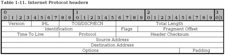
Version - bits 0-3. This is a version number of the IP protocol in binary. IPv4 iscalled 0100, while IPv6 is called 0110. This field is generally not used for filtering very much. The version described in RFC 791 is IPv4.
IHL (Internet Header Length) - bits 4-7. This field tells us how long the IP header is in 32 bit words. As you can see, we have split the header up in this way (32 bits per line) in the image as well. Since the Options field is of optional length, we can never be absolutely sure of how long the whole header is, without this field. The minimum length of this of the header is 5 words.
Type of Service, DSCP, ECN - bits 8-15. This is one of the most complex areas of the IP header for the simple reason that it has been updated 3 times. It has always had the same basic usage, but the implementation has changed several times. First the field was called the Type of Service field. Bit [0-2] of the field was called the Precedence field. Bit [3] was Normal/Low delay, Bit [4] was Normal/High throughput, Bit [5] was Normal/High reliability and bit [6-7] was reserved for future usage. This is still used in a lot of places with older hardware, and it still causes some problems for the Internet. Among other things, bit [6-7] are specified to be set to 0. In the ECN updates (RFC 3168, we start using these reserved bits and hence set other values than 0 to these bits. But a lot of old firewalls and routers have built in checks looking if these bits are set to 1, and if the packets do, the packet is discarded. Today, this is clearly a violation of RFC's, but there is not much you can do about it, except to complain.
The second iteration of this field was when the field was changed into the DS field as defined in RFC 2474. DS stands for Differentiated Services. According to this standard bits [0-5] is Differentiated Services Code Point (DSCP) and the remaining two bits [6-7] are still unused. The DSCP field is pretty much used the same as in how the ToS field was used before, to mark what kind of service this packet should be treated like if the router in question makes any difference between them. One big change is that a device must ignore the unused bits to be fully RFC 2474 compliant, which means we get rid of the previous hassle as explained previously, as long as the device creators follow this RFC.
The third, and almost last, change of the ToS field was when the two, previously, unused bits were used for ECN (Explicit Congestion Notification), as defined in RFC 3168. ECN is used to let the end nodes know about a routers congestion, before it actually starts dropping packets, so that the end nodes will be able to slow down their data transmissions, before the router actually needs to start dropping data. Previously, dropping data was the only way that a router had to tell that it was overloaded, and the end nodes had to do a slow restart for each dropped packet, and then slowly gather up speed again. The two bits are named ECT (ECN Capable Transport) and CE (Congestion Experienced) codepoints.
The final iteration of the whole mess is RFC 3260 which gives some new terminology and clarifications to the usage of the DiffServ system. It doesn't involve too many new updates or changes, except in the terminology. The RFC is also used to clarify some points that were discussed between developers.
Total Length - bits 16 - 31. This field tells us how large the packet is in octets, including headers and everything. The maximum size is 65535 octets, or bytes, for a single packet. The minimum packet size is 576 bytes, not caring if the packet arrives in fragments or not. It is only recommended to send larger packets than this limit if it can be guaranteed that the host can receive it, according to RFC 791. However, these days most networks runs at 1500 byte packet size. This includes almost all ethernet connections, and most Internet connections.
Identification - bits 32 - 46. This field is used in aiding the reassembly of fragmented packets.
Flags - bits 47 - 49. This field contains a few miscellaneous flags pertaining to fragmentation. The first bit is reserved, but still not used, and must be set to 0. The second bit is set to 0 if the packet may be fragmented, and to 1 if it may not be fragmented. The third and last bit can be set to 0 if this was the last fragment, and 1 if there are more fragments of this same packet.
Fragment Offset - bits 50 - 63. The fragment offset field shows where in the datagram that this packet belongs. The fragments are calculated in 64 bits, and the first fragment has offset zero.
Time to live - bits 64 - 72. The TTL field tells us how long the packet may live, or rather how many "hops" it may take over the Internet. Every process that touches the packet must remove one point from the TTL field, and if the TTL reaches zero, the whole packet must be destroyed and discarded. This is basically used as a safety trigger so that a packet may not end up in an uncontrollable loop between one or several hosts. Upon destruction the host should return an ICMP Time exceeded message to the sender.
Protocol - bits 73 - 80. In this field the protocol of the next level layer is indicated. For example, this may be TCP, UDP or ICMP among others. All of these numbers are defined by the Internet Assigned Numbers Authority. All numbers can befound on their homepage Internet Assigned Numbers Authority.
Header checksum - bits 81 - 96. This is a checksum of the IP header of the packet.This field is recomputed at every host that changes the header, which means pretty much every host that the packet traverses over, since they most often change the packets TTL field or some other.
Source address - bits 97 - 128. This is the source address field. It is generally written in 4 octets, translated from binary to decimal numbers with dots in between. That is for example, 127.0.0.1. The field lets the receiver know where the packet came from.
Destination address - bits 129 - 160. The destination address field contains the destination address, and what a surprise, it is formatted the same way as the source address.
Options - bits 161 - 192 <> 478. The options field is not optional, as it may sound. Actually, this is one of the more complex fields in the IP header. The options field contains different optional settings within the header, such as Internet timestamps, SACK or record route route options. Since these options are all optional, the Options field can have different lengths, and hence the whole IP header. However, since we always calculate the IP header in 32 bit words, we must always end the header on an even number, that is the multiple of 32. The field may contain zero or more options.
The options field starts with a brief 8 bit field that lets us know which options are used in the packet. The options are all listed in the TCP Options table, in the TCP options appendix. For more information about the different options, read the proper RFC's. For an updated listing of the IP options, check at Internet Assigned Numbers Authority.
Padding - bits variable. This is a padding field that is used to make the header end at an even 32 bit boundary. The field must always be set to zeroes straight through to the end.
TCP characteristics |
Page Up |
The TCP protocol resides on top of the IP protocol. It is a stateful protocol and has built-in functions to see that the data was received properly by the other end host. The main goals of the TCP protocol is to see that data is reliably received and sent, that the data is transported between the Internet layer and Application layer correctly, and that the packet data reaches the proper program in the application layer, and that the data reaches the program in the right order. All of this is possible through the TCP headers of the packet.
The TCP protocol looks at data as an continuous data stream with a start and a stop signal. The signal that indicates that a new stream is waiting to be opened is called a SYN three-way handshake in TCP, and consists of one packet sent with the SYN bit set. The other end then either answers with SYN/ACK or SYN/RST to let the client know if the connection was accepted or denied, respectively. If the client receives an SYN/ACK packet, it once again replies, this time with an ACK packet. At this point, the whole connection is established and data can be sent. During this initial handshake, all of the specific options that will be used throughout the rest of the TCP connection is also negotiated, such as ECN, SACK, etcetera.
While the datastream is alive, we have further mechanisms to see that the packets are actually received properly by the other end. This is the reliability part of TCP. This is done in a simple way, using a Sequence number in the packet. Every time we send a packet, we give a new value to the Sequence number, and when the other end receives the packet, it sends an ACK packet back to the data sender. The ACK packet acknowledges that the packet was received properly. The sequence number also sees to it that the packet is inserted into the data stream in a good order.
Once the connection is closed, this is done by sending a FIN packet from either end-point. The other end then responds by sending a FIN/ACK packet. The FIN sending end can then no longer send any data, but the other end-point can still finish sending data. Once the second end-point wishes to close the connection totally, it sends a FIN packet back to the originally closing end-point, and the other end-point replies with a FIN/ACK packet. Once this whole procedure is done, the connection is torn down properly.
As you will also later see, the TCP headers contain a checksum as well. The checksum consists of a simple hash of the packet. With this hash, we can with rather high accuracy see if a packet has been corrupted in any way during transit between the hosts.
TCP headers |
Page Up |
The TCP headers must be able to perform all of the tasks above. We have already explained when and where some of the headers are used, but there are still other areas that we haven't touched very deeply at. Below you see an image of the complete set of TCP headers. It is formatted in 32 bit words per row, as you can see.
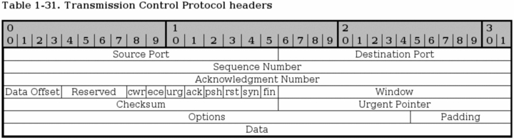
Source port - bit 0 - 15. This is the source port of the packet. The source port was originally bound directly to a process on the sending system. Today, we use a hash between the IP addresses, and both the destination and source ports to achieve this uniqueness that we can bind to a single application or program.
Destination port - bit 16 - 31. This is the destination port of the TCP packet. Just as with the source port, this was originally bound directly to a process on the receiving system. Today, a hash is used instead, which allows us to have more open connections at the same time. When a packet is received, the destination and source ports are reversed in the reply back to the originally sending host, so that destination port is now source port, and source port is destination port.
Sequence Number - bit 32 - 63. The sequence number field is used to set a number on each TCP packet so that the TCP stream can be properly sequenced (e.g., the packets winds up in the correct order). The Sequence number is then returned in the ACK field to ackonowledge that the packet was properly received.
Acknowledgment Number - bit 64 - 95. This field is used when we acknowledge a specific packet a host has received. For example, we receive a packet with one Sequence number set, and if everything is okey with the packet, we reply with an ACK packet with the Acknowledgment number set to the same as the original Sequence number.
Data Offset - bit 96 - 99. This field indicates how long the TCP header is, and where the Data part of the packet actually starts. It is set with 4 bits, and measures the TCP header in 32 bit words. The header should always end at an even 32 bit boundary, even with different options set. This is possible thanks to the Padding field at the very end of the TCP header.
Reserved - bit 100 - 103. These bits are reserved for future usage. In RFC 793 this also included the CWR and ECE bits. According to RFC 793 bit 100-105 (i.e., this and the CWR and ECE fields) must be set to zero to be fully compliant. Later on, when we started introducing ECN, this caused a lot of troubles because a lot of Internet appliances such as firewalls and routers dropped packets with them set. This is still true as of writing this.
CWR - bit 104. This bit was added in RFC 3268 and is used by ECN. CWR stands for Congestion Window Reduced, and is used by the data sending part to inform the receiving part that the congestion window has been reduced. When the congestion window is reduced, we send less data per timeunit, to be able to cope with the total network load.
ECE - bit 105. This bit was also added with RFC 3268 and is used by ECN. ECE stands for ECN Echo. It is used by the TCP/IP stack on the receiver host to let the sending host know that it has received an CE packet. The same thing applies here, as for the CWR bit, it was originally a part of the reserved field and because of this, some networking appliances will simply drop the packet if these fields contain anything else than zeroes. This is actually still true for a lot of appliances unfortunately.
URG - bit 106. This field tells us if we should use the Urgent Pointer field or not. If set to 0, do not use Urgent Pointer, if set to 1, do use Urgent pointer.
ACK - bit 107. This bit is set to a packet to indicate that this is in reply to another packet that we received, and that contained data. An Acknowledgment packet is always sent to indicate that we have actually received a packet, and that it contained no errors. If this bit is set, the original data sender will check the Acknowledgment Number to see which packet is actually acknowledged, and then dump it from the buffers.
PSH - bit 108. The PUSH flag is used to tell the TCP protocol on any intermediate hosts to send the data on to the actual user, including the TCP implementation on the receiving host. This will push all data through, unregardless of where or how much of the TCP Window that has been pushed through yet.
RST - bit 109. The RESET flag is set to tell the other end to tear down the TCP connection. This is done in a couple of different scenarios, the main reasons being that the connection has crashed for some reason, if the connection does not exist, or if the packet is wrong in some way.
SYN - bit 110. The SYN (or Synchronize sequence numbers) is used during the initial establishment of a connection. It is set in two instances of the connection, the initial packet that opens the connection, and the reply SYN/ACK packet. It should never be used outside of those instances.
FIN - bit 111. The FIN bit indicates that the host that sent the FIN bit has no more data to send. When the other end sees the FIN bit, it will reply with a FIN/ACK. Once this is done, the host that originally sent the FIN bit can no longer send any data. However, the other end can continue to send data until it is finished, and will then send a FIN packet back, and wait for the final FIN/ACK, after which the connection is sent to a CLOSED state.
Window - bit 112 - 127. The Window field is used by the receiving host to tell the sender how much data the receiver permits at the moment. This is done by sending an ACK back, which contains the Sequence number that we want to acknowledge, and the Window field then contains the maximum accepted sequence numbers that the sending host can use before he receives the next ACK packet. The next ACK packet will update accepted Window which the sender may use.
Checksum - bit 128 - 143. This field contains the checksum of the whole TCP header. It is a one's complement of the one's complement sum of each 16 bit word in the header. If the header does not end on a 16 bit boundary, the additional bits are set to zero. While the checksum is calculated, the checksum field is set to zero. The checksum also covers a 96 bit pseudoheader containing the Destination-, Source-address, protocol, and TCP length. This is for extra security.
Urgent Pointer - bit 144 - 159. This is a pointer that points to the end of the data which is considered urgent. If the connection has important data that should be processed as soon as possible by the receiving end, the sender can set the URG flag and set the Urgent pointer to indicate where the urgent data ends.
Options - bit 160 - **. The Options field is a variable length field and contains optional headers that we may want to use. Basically, this field contains 3 subfields at all times. An initial field tells us the length of the Options field, a second field tells us which options are used, and then we have the actual options. A complete listing of all the TCP Options can be found in TCP options.
Padding - bit **. The padding field pads the TCP header until the whole header ends at a 32-bit boundary. This ensures that the data part of the packet begins on a 32-bit boundary, and no data is lost in the packet. The padding always consists of only zeros.
UDP characteristics |
Page Up |
The User Datagram Protocol (UDP) is a very basic and simple protocol on top of the IP protocol. It was developed to allow for very simple data transmission without any error detection of any kind, and it is stateless. However, it is very well fit for query/response kind of applications, such as for example DNS, et cetera, since we know that unless we get a reply from the DNS server, the query was lost somewhere. Sometimes it may also be worth using the UDP protocol instead of TCP, such as when we want only error/loss detection but don't care about sequencing of the packets. This removes some overhead that comes from the TCP protocol. We may also do the other thing around, make our own protocol on top of UDP that only contains sequencing, but no error or loss detection.
The UDP protocol is specified in RFC 768 - User Datagram Protocol. It is a very short and brief RFC, which fits a simple protocol like this very well.
UDP headers |
Page Up |
The UDP header can be said to contain a very basic and simplified TCP header. It contains destination-, source-ports, header length and a checksum as seen in the image below.

Source port - bit 0-15. This is the source port of the packet, describing where a reply packet should be sent. This can actually be set to zero if it doesn't apply. For example, sometimes we don't require a reply packet, and the packet can then be set to source port zero. In most implementations, it is set to some port number.
Destination port - bit 16-31. The destination port of the packet. This is required for all packets, as opposed to the source port of a packet.
Length - bit 32-47. The length field specifies the length of the whole packet in octets, including header and data portions. The shortest possible packet can be 8 octets long.
Checksum - bit 48-63. The checksum is the same kind of checksum as used in the TCP header, except that it contains a different set of data. In other words, it is a one's complement of the one's complement sum of parts of the IP header, the whole UDP header, theUDP data and padded with zeroes at the end when necessary.
ICMP characteristics |
Page Up |
ICMP messages are used for a basic kind of error reporting between host to host, or host to gateway. Between gateway to gateway, a protocol called Gateway to Gateway protocol (GGP) should normally be used for error reporting. As we have already discussed, the IP protocol is not designed for perfect error handling, but ICMP messages solves some parts of these problems. The big problem from one standpoint is that the headers of the ICMP messages are rather complicated, and differ a little bit from message to message. However, this will not be a big problem from a filtering standpoint most of the time.
The basic form is that the message contains the standard IP header, type, code and a checksum. All ICMP messages contains these fields. The type specifies what kind of error or reply message this packet is, such as for example destination unreachable, echo, echo reply, or redirect message. The code field specifies more information, if necessary. If the packet is of type destination unreachable, there are several possible values on this code field such as network unreachable, host unreachable, or port unreachable. The checksum is simply a checksum for the whole packet.
As you may have noticed, I mentioned the IP header explicitly for the ICMP packet. This was done since the actual IP header is an integral part of the ICMP packet, and the ICMP protocol lives on the same level as the IP protocol in a sense. ICMP does use the IP protocol as if it where a higher level protocol, but at the same time not. ICMP is an integral part of IP, and ICMP must be implemented in every IP implementation.
ICMP headers |
Page Up |
As already explained, the headers differs a little bit from ICMP type to ICMP type. Most of the ICMP types are possible to group by their headers. Because of this, we will discuss the basic header form first, and then look at the specifics for each group of types that should be discussed.
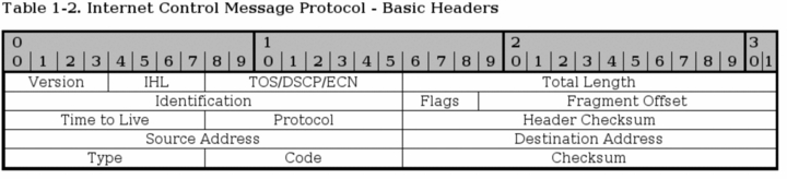
All packets contain some basic values from the IP headers discussed previously in this chapter. The headers have previously been discussed at some length, so this is just a short listing of the headers, with a few notes about them.
-
Version - This should always be set to 4.
-
Internet Header Length - The length of the header in 32 bit words.
-
Type of Service - See above. This should be set to 0, as this is the only legit setting according to RFC 792 - Internet Control Message Protocol.
-
Total Length - Total length of the header and data portion of the packet, counted in octets.
-
Identification , Flags and Fragment offsets - Ripped from the IP protocol.
-
Time To Live - How many hops this packet will survive.
-
Protocol - which version of ICMP is being used (should always be 1).
-
Header Checksum - See the IP explanation.
-
Source Address - The source address from whom the packet was sent. This is not entirely true, since the packet can have another source address, than that which is located on the machine in question. The ICMP types that can have this effect will be noted if so.
-
Destination Address - The destination address of the packet.
There are also a couple of new headers that are used by all of the ICMP types. The new headers are as follows, this time with a few more notes about them:
-
Type - The type field contains the ICMP type of the packet. This is always different from ICMP type to type. For example ICMP Destination Unreachable packets will have a type 3 set to it. For a complete listing of the different ICMP types, see the ICMP types appendix. This field contains 8 bits total.
-
Code - All ICMP types can contain different codes as well. Some types only have a single code, while others have several codes that they can use. For example, the ICMP Destination Unreachable (type 3) can have at least code 0, 1, 2, 3, 4 or 5 set. Each code has a different meaning in that context then. For a complete listing of the different codes, see the ICMP types appendix. This field is 8 bits in length, total. We will discuss the different codes a little bit more in detail for each type later on in this section.
-
Checksum - The Checksum is a 16 bit field containing a one's complement of the ones complement of the headers starting with the ICMP type and down. While calculating the checksum, the checksum field should be set to zero.
At this point the headers for the different packets start to look different also. We will describe the most common ICMP Types one by one, with a brief discussion of its headers and different codes.
ICMP Echo Request/Reply
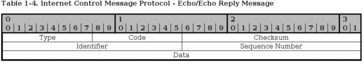
I have chosen to speak about both the reply and the request of the ICMP echo packets here since they are so closely related to each other. The first difference is that the echo request is type 8, while echo reply is type 0. When a host receives a type 8, it replies with a type 0.
When the reply is sent, the source and destination addresses switch places as well. After both of those changes has been done, the checksum is recomputed, and the reply is sent. There is only one code for both of these types, they are always set to 0.
-
Identifier - This is set in the request packet, and echoed back in the reply, to be able to keep different ping requests and replies together.
-
Sequence number - The sequence number for each host, generally this starts at 1 and is incremented by 1 for each packet.
The packets also contains a data part. Per default, the data part is generally empty, but it can contain a userspecified amount of random data.
ICMP Destination Unreachable

The first three fields seen in the image are the same as previously described. The Destination Unreachable type has 16 basic codes that can be used, as seen below in the list.
-
Code 0 - Network unreachable - Tells you if a specific network is currently unreachable.
-
Code 1 - Host unreachable - Tells you if a specific host is currently unreachable.
-
Code 2 - Protocol unreachable - This code tells you if a specific protocol (tcp, udp, etc) can not be reached at the moment.
-
Code 3 - Port unreachable - If a port (ssh, http, ftp-data, etc) is not reachable, you will get this message.
-
Code 4 - Fragmentation needed and DF set - If a packet needs to be fragmented to be delivered, but the Do not fragment bit is set in the packet, the gateway will return this message.
-
Code 5 - Source route failed - If a source route failed for some reason, this message is returned.
-
Code 6 - Destination network unknown - If there is no route to a specific network, this message is returned.
-
Code 7 - Destination host unknown - If there is no route to a specific host, this message is returned.
-
Code 8 - Source host isolated (obsolete) - If a host is isolated, this message should be returned. This code is obsoleted today.
-
Code 9 - Destination network administratively prohibited - If a network was blocked at a gateway and your packet was unable to reach it because of this, you should get this ICMP code back.
-
Code 10 - Destination host administratively prohibited - If you where unable to reach a host because it was administratively prohibited (e.g., routing administration), you will get this message back.
-
Code 11 - Network unreachable for TOS - If a network was unreachable because of a bad TOS setting in your packet, this code will be generated as a return packet.
-
Code 12 - Host unreachable for TOS - If your packet was unable to reach a host because of the TOS of the packet, this is the message you get back.
-
Code 13 - Communication administratively prohibited by filtering - If the packet was prohibited by some kind of filtering (e.g., firewalling), we get a code 13 back.
-
Code 14 - Host precedence violation - This is sent by the first hop router to notify a connected host, to notify the host that the used precedence is not permitted for a specific destination/source combination.
-
Code 15 - Precedence cutoff in effect - The first hop router may send this message to a host if the datagram it received had a too low precedence level set in it.
On top of this, it also contains a small "data" part, which should be the whole Internet header (IP header) and 64 bits of the original IP datagram. If the next level protocol contains any ports, etc, it is assumed that the ports should be available in the extra 64 bits.
Source Quench

A source quench packet can be sent to tell the originating source of a packet or stream of packets to slow down when continuing to send data. Note that gateway or destination host that the packets traverses can also be quiet and silently discard the packets, instead of sending any source quench packets.
This packet contains no extra header except the data portion, which contains the internet header plus 64 bits of the original data datagram. This is used to match the source quench message to the correct process, which is currently sending data through the gateway or to the destination host.
All source quench packets have their ICMP types set to 4. They have no codes except 0.
|
|
Today, there are a couple of new possible ways of notifying the sending and receiving host that a gateway or destination host is overloaded. One way for example is the ECN (Explicit Congestion Notification) system. |
Redirect

The ICMP Redirect type is sent in a single case. Consider this, you have a network (192.168.0.0/24) with several clients and hosts on it, and two gateways. One gateway to a 10.0.0.0/24 network, and a default gateway to the rest of the Internet. Now consider if one of the hosts on the 192.168.0.0/24 network has no route set to 10.0.0.0/24, but it has the default gateway set. It sends a packet to the default gateway, which of course knows about the 10.0.0.0/24 network. The default gateway can deduce that it is faster to send the packet directly to the 10.0.0.0/24 gateway since the packet will enter and leave the gateway on the same interface. The default gateway will hence send out a single ICMP Redirect packet to the host, telling it about the real gateway, and then sending the packet on to the 10.0.0.0/24 gateway. The host will now know about the closest 10.0.0.0/24 gateway, and hopefully use it in the future.
The main header of the Redirect type is the Gateway Internet Address field. This field tells the host about the proper gateway, which should really be used. The packet also contains the IP header of the original packet, and the 64 first bits of data in the original packet, which is used to connect it to the proper process sending the data.
The Redirect type has 4 different codes as well, these are the following.
-
Code 0 - Redirect for network - Only used for redirects for a whole network (e.g., the example above).
-
Code 1 - Redirect for host - Only used for redirects of a specific host (e.g., a host route).
-
Code 2 - Redirect for TOS and network - Only used for redirects of a specific Type of Service and to a whole network. Used as code 0, but also based on the TOS.
-
Code 3 - Redirect for TOS and host - Only used for redirects of a specific Type of Service and to a specific host. Used as code 1, but also based on the TOS in other words.
TTL equals 0
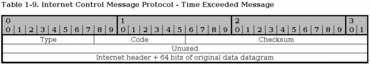
The TTL equals 0 ICMP type is also known as Time Exceeded Message and has type 11 set to it, and has 2 ICMP codes available. If the TTL field reaches 0 during transit through a gateway or fragment reassembly on the destination host, the packet must be discarded. To notify the sending host of this problem, we can send a TTL equals 0 ICMP packet. The sender can then raise the TTL of outgoing packets to this destination if necessary.
The packet only contains the extra data portion of the packet. The data field contains the Internet header plus 64 bits of the data of the IP packet, so that the other end may match the packet to the proper process. As previously mentioned, the TTL equals 0 type can have two codes.
-
Code 0 - TTL equals 0 during transit - This is sent to the sending host if the original packet TTL reached 0 when it was forwarded by a gateway.
-
Code 1 - TTL equals 0 during reassembly - This is sent if the original packet was fragmented, and TTL reached 0 during reassembly of the fragments. This code should only be sent from the destination host.
Parameter problem
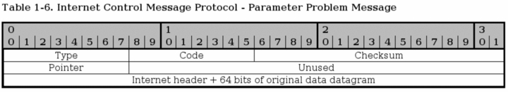
The parameter problem ICMP uses type 12 and it has 2 codes that it uses as well. Parameter problem messages are used to tell the sending host that the gateway or receiving host had problems understanding parts of the IP headers such as errors, or that some required options where missing.
The parameter problem type contains one special header, which is a pointer to the field that caused the error in the original packet, if the code is 0 that is. The following codes are available:
-
Code 0 - IP header bad (catchall error) - This is a catchall error message as discussed just above. Together with the pointer, this code is used to point to which part of the IP header contained an error.
-
Code 1 - Required options missing - If an IP option that is required is missing, this code is used to tell about it.
Timestamp request/reply

The timestamp type is obsolete these days, but we bring it up briefly here. Both the reply and the request has a single code (0). The request is type 13 while the reply is type 14. The timestamp packets contains 3 32-bit timestamps counting the milliseconds since midnight UT (Universal Time).
The first timestamp is the Originate timestamp, which contains the last time the sender touched the packet. The receive timestamp is the time that the echoing host first touched the packet and the transmit timestamp is the last timestamp set just previous to sending the packet.
Each timestamp message also contains the same identifiers and sequence numbers as the ICMP echo packets.
Information request/reply
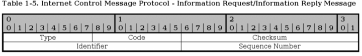
The information request and reply types are obsolete since there are protocols on top of the IP protocol that can now take care of this when necessary (DHCP, etc). The information request generates a reply from any answering host on the network that we are attached to.
The host that wishes to receive information creates a packet with the source address set to the network we are attached to (for example, 192.168.0.0), and the destination network set to 0. The reply will contain information about our numbers (netmask and ip address).
The information request is run through ICMP type 15 while the reply is sent via type 16.
SCTP Characteristics |
Page Up |
Stream Control Transmission Protocol (SCTP) is a relatively new protocol in the game, but since it is growing in usage and complements the TCP and UDP protocols, I have chosen to add this section about it. It has an even higher reliability than TCP, and at the same time a lower overhead from protocol headers.
SCTP has a couple of very interesting features that can be interesting. For those who wish to learn more about this, read the RFC 3286 - An Introduction to the Stream Control Transmission Protocol and RFC 2960 - Stream Control Transmission Protocol document. The first document is an introduction to SCTP and should be very interesting to people who are still in need of more information. The second document is the actual specification for the protocol, which might be less interesting unless you are developing for the protocol or are really interested.
The protocol was originally developed for Telephony over IP, or Voice over IP (VoIP), and has some very interesting attributes due to this. Industry grade VoIP requires very high reliability for one, and this means that a lot of resilience has to be built into the system to handle different kind of problems. The following is a list of the basic features of SCTP.
-
Unicast with Multicast properties. This means it is a point-to-point protocol but with the ability to use several addresses at the same end host. It can in other words use different paths to reach the end host. TCP in comparison breaks if the transport path breaks, unless the IP protocol corrects it.
-
Reliable transmission. It uses checksums and SACK to detect corrupted, damaged, discarded, duplicated and reordered data. It can then retransmit data as necessary. This is pretty much the same as TCP, but SCTP is more resilient when it comes to reordered data and allows for faster pickups.
-
Message oriented. Each message can be framed and hence you can keep tabs on the structure and order of the datastream. TCP is byte oriented and all you get is a stream of bytes without any order between different data inside. You need an extra layer of abstraction in TCP in other words.
-
Rate adaptive. It is developed to cooperate and co-exist with TCP for bandwidth. It scales up and down based on network load conditions just the same as TCP. It also has the same algorithms for slow starting when packets where lost. ECN is also supported.
-
Multi-homing. As previously mentioned, it is able to set up different end nodes directly in the protocol, and hence doesn't have to rely on the IP layer for resilience.
-
Multi-streaming. This allows for multiple simultaneous streams inside the same stream. Hence the name Stream Control Transmission Protocol. A single stream can for example be opened to download a single webpage, and all the images and html documents can then be downloaded within the same stream simultaneously. Or why not a database protocol which can create a separate control stream and then use several streams to receive the output from the different queries simultaneously.
-
Initiation. 4 packet initiation of connections where packet 3 and 4 can be used to send data. The equivalent of syncookies is implemented by default to avoid DoS attacks. INIT collision resolution to avoid several simultaneous SCTP connections.
This list could be made even longer, but I will not. Most of this information is gathered from the RFC 3286 - An Introduction to the Stream Control Transmission Protocol document, so read on there for more information.
|
|
In SCTP we talk about chunks, not packets or windows anymore. An SCTP frame can contain several different chunks since the protocol is message oriented. A chunk can either be a control or a data chunk. Control chunks is used to control the session, and data chunks are used to send actual data. |
Initialization and association
Each connection is initialized by creating an association between the two hosts that wants to talk to each other. This association is initialized when a user needs it. It is later used as needed.
The initialization is done through 4 packets. First an INIT chunk is sent, which is replied to with an INIT ACK containing a cookie, after this the connection can start sending data. However, two more packets are sent in the initialization. The cookie is replied to with a COOKIE ECHO chunk, which is finally replied to with a COOKIE ACK chunk.
Data sending and control session
SCTP can at this point send data. In SCTP there are control chunks and data chunks, as previously stated. Data chunks are sent using DATA chunks, and DATA chunks are acknowledged by sending a SACK chunk. This works practically the same as a TCP SACK. SACK chunks are control chunks.
On top of this, there are some other control chunks that can be seen. HEARTBEAT and HEARTBEAT ACK chunks for one, and ERROR chunks for another. HEARTBEATs are used to keep the connection alive, and ERROR is used to inform of different problems or errors in the connection, such as invalid stream id's or missing mandatory parameters et cetera.
Shutdown and abort
The SCTP connection is finally closed by either an ABORT chunk or by a graceful SHUTDOWN chunk. SCTP doesn't have a half-closed state as TCP, in other words one side can not continue sending data while the other end has closed its sending socket.
When the user/application wants to close the SCTP socket gracefully, it tells the protocol to SHUTDOWN. SCTP then sends all the data still in its buffers, and then sends a SHUTDOWN chunk. When the other end receives the SHUTDOWN, it will stop accepting data from the application and finish sending all the data. Once it has gotten all the SACK's for the data, it will send a SHUTDOWN ACK chunk and once the closing side has received this chunk, it will finally reply with a SHUTDOWN COMPLETE chunk. The whole session is now closed.
Another way of closing a session is to ABORT it. This is an ungraceful way of removing an SCTP association. When a connecting party wants to remove an SCTP association instantaneously, it sends an ABORT chunk with all the right values signed. All data in the buffers et cetera will be discarded and the association will then be removed. The receiving end will do the same after verifying the ABORT chunk.
SCTP Headers |
Page Up |
This will be a very brief introduction to the SCTP headers. SCTP has a lot of different types of packets, and hence I will try to follow the RFC's as close as possible and how they depict the different headers, starting with a general overview of the headers applicable to all SCTP packets.
SCTP Generic header format

This is a generic overview of how a SCTP packet is laid out. Basically, you have a common header first with information describing the whole packet, and the source and destination ports etc. See more below for information on the common header.
After the common header a variable number of chunks are sent, up to the maximum possible in the MTU. All chunks can be bundled except for INIT, INIT ACK and SHUTDOWN COMPLETE, which must not be bundled. DATA chunks may be broken down to fit inside the MTU of the packets.
SCTP Common and generic headers
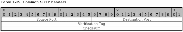
Every SCTP packet contains the Common header as seen above. The header contains four different fields and is set for every SCTP packet.
Source port - bit 0-15. This field gives the source port of the packet, which port it was sent from. The same as for TCP and UDP source port.
Destination port - bit 16-31. This is the destination port of the packet, ie., the port that the packet is going to. It is the same as for the TCP and UDP destination port.
Verification Tag - bit 32-63. The verification tag is used to verify that the packet comes from the correct sender. It is always set to the same value as the value received by the other peer in the Initiate Tag during the association initialization, with a few exceptions:
-
An SCTP packet containing an INIT chunk must have the Verification tag set to 0.
-
A SHUTDOWN COMPLETE chunk with the T-bit set must have the verification tag copied from the verification tag of the SHUTDOWN-ACK chunk.
-
Packets containing ABORT chunk may have the verification tag set to the same verification tag as the packet causing the ABORT.
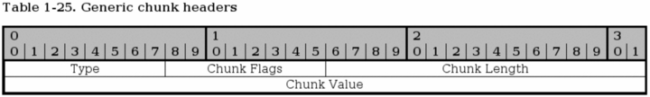
All SCTP chunks has a special layout that they all adhere to as can be seen above. This isn't an actual header, but rather a formalized way of how they do look.
Type - bit 0-7. This field specifies the chunk type of the packet, for example is it an INIT or SHUTDOWN chunk or what? Each chunk type has a specific number, and is specified in the image below. Here is a complete list of Chunk types:
Table 2-1. SCTP Types
| Chunk Number | Chunk Name |
|---|---|
| 0 | Payload Data (DATA) |
| 1 | Initiation (INIT) |
| 2 | Initiation Acknowledgement (INIT ACK) |
| 3 | Selective Acknowledgement (SACK) |
| 4 | Heartbeat Request (HEARTBEAT) |
| 5 | Heartbeat Acknowledgement (HEARTBEAT ACK) |
| 6 | Abort (ABORT) |
| 7 | Shutdown (SHUTDOWN) |
| 8 | Shutdown Acknowledgement (SHUTDOWN ACK) |
| 9 | Operation Error (ERROR) |
| 10 | State Cookie (COOKIE ECHO) |
| 11 | Cookie Acknowledgement (COOKIE ACK) |
| 12 | Reserved for Explicit Congestion Notification Echo (ECNE) |
| 13 | Reserved for Congestion Window Reduced (CWR) |
| 14 | Shutdown Complete (SHUTDOWN COMPLETE) |
| 15-62 | Reserved for IETF |
| 63 | IETF-defined chunk extensions |
| 64-126 | reserved to IETF |
| 127 | IETF-defined chunk extensions |
| 128-190 | reserved to IETF |
| 191 | IETF-defined chunk extensions |
| 192-254 | reserved to IETF |
| 255 | IETF-defined chunk extensions |
Chunk Flags - bit 8-15. The chunk flags are generally not used but are set up for future usage if nothing else. They are chunk specific flags or bits of information that might be needed for the other peer. According to specifications, flags are only used in DATA, ABORT and SHUTDOWN COMPLETE packets at this moment. This may change however.
 |
A lot of times when you read an RFC, you might run into some old proven problems. The RFC 2960 - Stream Control Transmission Protocol document is one example of this, where they specifically specify that the Chunk flags should always be set to 0 and ignored unless used for something. This is written all over the place, and it begs for problems in the future. If you do firewalling or routing, watch out very carefully for this, since specifications for fields like this may change in the future and hence break at your firewall without any legit reason. This happened before with the implementation of ECN in the IP headers for example. See more in the IP headers section of this chapter. |
Chunk Length - bit 16-31. This is the chunk length calculated in bytes. It includes all headers, including the chunk type, chunk flags, chunk length and chunk value. If there is no chunk value, the chunk length will be set to 4 (bytes).
Chunk Value - bit 32-n. This is specific to each chunk and may contain more flags and data pertaining to the chunk type. Sometimes it might be empty, in which case the chunk length will be set to 4.
SCTP ABORT chunk
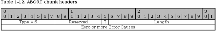
The ABORT chunk is used to abort an association as previously described in the Shutdown and abort section of this chapter. ABORT is issued upon unrecoverable errors in the association such as bad headers or data.
Type - bit 0-7. Always set to 6 for this chunk type.
Reserved - bit 8-14. Reserved for future chunk flags but not used as of writing this. See the SCTP Common and generic headers for more information about the chunk flags field.
T-bit - bit 15. If this bit is set to 0, the sender had a TCB associated with this packet that it has destroyed. If the sender had no TCB the T-bit should be set to 1.
Length - bit 16-31. Sets the length of the chunk in bytes including error causes.
SCTP COOKIE ACK chunk

The COOKIE ACK chunk is used during the initialization of the connection and never anywhere else in the connection. It must precede all DATA and SACK chunks but may be sent in the same packet as the first of these packets.
Type - bit 0-7. Always set to 11 for this type.
Chunk flags - bit 8-15. Not used so far. Should always be set to 0 according to RFC 2960 - Stream Control Transmission Protocol. You should always watch out for this kind of specific behaviour stated by RFC's since it might change in the future, and hence break your firewalls etc. Just the same as happened with IP and ECN. See the SCTP Common and generic headers section for more information.
Length - bit 16-31. Should always be 4 (bytes) for this chunk.
SCTP COOKIE ECHO chunk
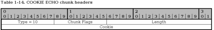
The COOKIE ECHO chunk is used during the initialization of the SCTP connection by the initiating party to reply to the cookie sent by the responding party in the State cookie field in the INIT ACK packet. It may be sent together with DATA chunks in the same packet, but must precede the DATA chunks in such case.
Type - bit 0-7. The chunk type is always set to 10 for this chunk.
Chunk flags - bit 8-15. This field is not used today. The RFC specifies that the flags should always be set to 0, but this might cause trouble as can be seen in the SCTP Common and generic headers section above, specifically the Chunk flags explanation.
Length - bit 16-31. Specifies the length of the chunk, including type, chunk flags, length and cookie fields in bytes.
Cookie - bit 32-n. This field contains the cookie as sent in the previous INIT ACK chunk. It must be the exact same as the cookie sent by the responding party for the other end to actually open the connection. The RFC 2960 - Stream Control Transmission Protocol specifies that the cookie should be as small as possible to insure interoperability, which is very vague and doesn't say much.
SCTP DATA chunk

DATA chunks are used to send actual data through the stream and have rather complex headers in some ways, but not really worse than TCP headers in general. Each DATA chunk may be part of a different stream, since each SCTP connection can handle several different streams.
Type - bit 0-7. The Type field should always be set to 0 for DATA chunks.
Reserved - bit 8-12. Not used today. Might be applicable for change. See SCTP Common and generic headers for more information.
U-bit - bit 13. The U-bit is used to indicate if this is an unordered DATA chunk. If it is, the Stream Sequence Number must be ignored by the receiving host and send it on to the upper layer without delay or tries to re-order the DATA chunks.
B-bit - bit 14. The B-bit is used to indicate the beginning of a fragmented DATA chunk. If this bit is set and the E (ending) bit is not set, it indicates that this is the first fragment of a chunk that has been fragmented into several DATA chunks.
E-bit - bit 15. The E-bit is used to indicate the ending of a fragmented DATA chunk. If this flag is set on a chunk, it signals to the SCTP receiver that it can start reassembling the fragments and pass them on to the upper layer. If a packet has both the BE-bits set to set to 0, it signals that the chunk is a middle part of a fragmented chunk. If both BE-bits are set to 1 it signals that the packet is unfragmented and requires no reassembly et cetera.
Length - bit 16-31. The length of the whole DATA chunk calculated in bytes,including the chunk type field and on until the end of the chunk.
TSN - bit 32-63. The Transmission Sequence Number (TSN) is sent in the DATA chunk, and the receiving host uses the TSN to acknowledge that the chunk got through properly by replying with a SACK chunk. This is an overall value for the whole SCTP association.
Stream Identifier - bit 64-79. The Stream Identifier is sent along with the DATA chunk to identify which stream the DATA chunk is associated with. This is used since SCTP can transport several streams within a single association.
Stream Sequence Number - bit 80-95. This is the sequence number of the chunk for the specific stream identified by the Stream Identifier. This sequence number is specific for each stream identifier. If a chunk has been fragmented, the Stream Sequence Number must be the same for all fragments of the original chunk.
Payload Protocol Identifier - bit 96-127. This value is filled in by the upper layers, or applications using the SCTP protocol as a way to identify to each other the content of the DATA chunk. The field must always be sent, including in fragments since routers and firewalls, et cetera, on the way might need the information. If the value was set to 0, the value was not set by the upper layers.
User data - bit 128-n. This is the actual data that the chunk is transporting. It can be of variable length, ending on an even octet. It is the data in the stream as specified by the stream sequence number n in the stream S.
SCTP ERROR chunk
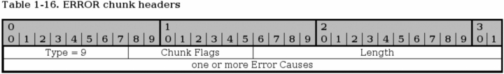
The ERROR chunk is sent to inform the other peer of any problems within the current stream. Each ERROR chunk can contain one or more Error Causes, which are more specifically detailed in the RFC 2960 - Stream Control Transmission Protocol document. I will not go into further details here than the basic ERROR chunk, since it would be too much information. The ERROR chunk is not fatal in and of itself, but rather details an error that has happened. It may however be used together with an ABORT chunk to inform the peer of the error before killing the connection.
Type - bit 0-7. This value is always set to 9 for ERROR chunks.
Chunk flags - bit 8-15. Not used today. Might be applicable for change. See SCTP Common and generic headers for more information.
Length - bit 16-31. Specifies the length of the chunk in bytes, including all the Error Causes.
Error causes - bit 32-n. Each ERROR chunk may contain one or more Error Causes, which notifies the opposite peer of a problem with the connection. Each Error Cause follows a specific format, as described in the RFC 2960 - Stream Control Transmission Protocol document. We will not go into them here more than to say that they all contain an Cause Code, cause length and cause specific information field. The following Error Causes are possible:
Table 2-2. Error Causes
| Cause Value | Chunk Code |
|---|---|
| 1 | Invalid Stream Identifier |
| 2 | Missing Mandatory Parameter |
| 3 | Stale Cookie Error |
| 4 | Out of Resource |
| 5 | Unresolvable Address |
| 6 | Unrecognized Chunk Type |
| 7 | Invalid Mandatory Parameter |
| 8 | Unrecognized Parameters |
| 9 | No User Data |
| 10 | Cookie Received While Shutting Down |
SCTP HEARTBEAT chunk
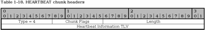
The HEARTBEAT chunk is sent by one of the peers to probe and find out if a specific SCTP endpoint address is up. This is sent to the different addresses that was negotiated during the initialization of the association to find out if they are all up.
Type - bit 0-7. The type is always set to 4 for HEARTBEAT chunks.
Chunk flags - bit 8-15. Not used today. Might be applicable for change. See SCTP Common and generic headers for more information.
Length - bit 16-31. The length of the whole chunk, including the Heartbeat Information TLV.
Heartbeat Information TLV - bit 32-n. This is a variable-length parameter as defined inside the RFC 2960 - Stream Control Transmission Protocol document. This is a mandatory parameter for the HEARTBEAT chunks that contains 3 fields, info type = 1, info length and a sender-specific Heartbeat Information parameter. The last field should be a sender-specific information field of some kind, for example a timestamp when the heartbeat was sent and a destination IP address. This is then returned in the HEARTBEAT ACK chunk.
SCTP HEARTBEAT ACK chunk
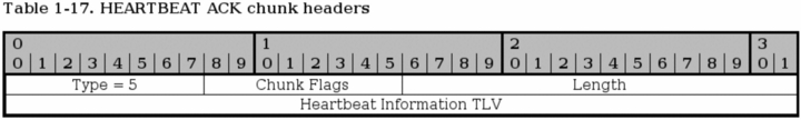
The HEARTBEAT ACK is used to acknowledge that a HEARTBEAT was received and that the connection is working properly. The chunk is always sent to the same IP address as the request was sent from.
Type - bit 0-7. Always set to 5 for HEARTBEAT ACK chunks.
Chunk flags - bit 8-15. Not used today. Might be applicable for change. See SCTP Common and generic headers for more information.
Chunk length - bit 16-31. The length of the HEARTBEAT ACK chunk including the Heartbeat Information TLV, calculated in bytes.
Heartbeat Information TLV - bit 32-n. This field must contain the Heartbeat Information parameter that was sent in the original HEARTBEAT chunk.
SCTP INIT chunk
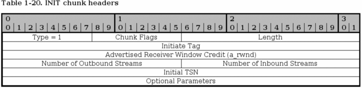
The INIT chunk is used to initiate a new association with a destination host, and is the first chunk to be sent by the connecting host. The INIT chunk contains several mandatory fixed length parameters, and some optional variable length parameters. The fixed length mandatory parameters are already in the above headers, and are the Initiate Tag, Advertised Receiver Window Credit, Number of Outbound Streams, Number of Inbound Streams and the Initial TSN parameters. After this comes a couple of optional parameters, they will be listed with the optional parameters paragraph below.
Type - bit 0-7. The type field is always set to 1 for INIT chunks.
Chunk flags - bit 8-15. Not used today. Might be applicable for change. See SCTP Common and generic headers for more information.
Chunk Length - bit 16-31. The chunk length is the length of the whole packet, including everything in the headers, including the optional parameters.
Initiate Tag - bit 32-63. The Initiate Tag is set within the INIT chunk and must be used by the receiver to acknowledge all packets henceforth, within the Verification Tag of the established association. The Initiate Tag may take any value except 0. If the value is 0 anyways, the receiver must react with an ABORT.
Advertised Receiver Window Credit (a_rwnd)- bit 64-95. This is the minimum receiving buffer that the sender of the INIT chunk will allocate for this association, in bytes. This can then be used by the receiver of the a_rwnd, to know how much data it can send out without being SACK'ed. This window should not be lessened, but it might by sending the new a_rwnd in a SACK chunk.
Number of Outbound Streams - bit 96-111. This specifies the maximum number of outbound streams that the connecting host wishes to create to the receiving host. The value must not be 0, and if it is, the receiving host should ABORT the association immediately. There is no negotiation of the minimum number of outbound or inbound streams, it is simply set to the lowest that either host has set in the header.
Number of Inbound Streams - bit 112-127. Specifies the maximum number of inbound connections that the sending peer will allow the receiving host to create in this association. This must not be set to 0, or the receiving host should ABORT the connection. There is no negotiation of the minimum number of outbound or inbound streams, it is simply set to the lowest that either host has set in the header.
Initial TSN - bit 128-159. This value sets the initial Transmit Sequence Number (TSN) that the sender will use when sending data. The field may be set to the same value as the Initiate Tag.
On top of the above mandatory fixed length headers, there are also some optional variable length parameters that might be set, and at least one of the IPv4, IPv6 or Hostname parameters must be set. Only one Hostname may be set, and if a Hostname is set, no IPv4 or IPv6 parameters may be set. Multiple IPv4 and IPv6 parameters may also be set in the same INIT chunk. Also, none of these parameters needs to be set in case the sender only has one address that can be reached, which is where the chunk should be coming from. These parameters are used to set up which addresses may be used to connect to the other end of the association. This is a full list of all the parameters available in the INIT chunk:
Table 2-3. INIT Variable Parameters
| Parameter Name | Status | Type Value |
|---|---|---|
| IPv4 Address | Optional | 5 |
| IPv6 Address | Optional | 6 |
| Cookie Preservative | Optional | 9 |
| Host Name Address | Optional | 11 |
| Supported Address Types | Optional | 12 |
| Reserved for ECN Capable | Optional | 32768 |
Below we describe the three most common Parameters used in the INIT chunk.

The IPv4 parameter is used to send an IPv4 address in the INIT chunk. The IPv4 address can be used to send data through the association. Multiple IPv4 and IPv6 addresses can be specified for a single SCTP association.
Parameter Type - bit 0-15. This is always set to 5 for IPv4 address parameters.
Length - bit 16-31. This is always set to 8 for IPv4 address parameters.
IPv4 Address - bit 32-63. This is an IPv4 address of the sending endpoint.
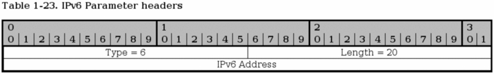
This parameter is used to send IPv6 addresses in the INIT chunk. This address can then be used to contact the sending endpoint with this association.
Type - bit 0-15. Always set to 6 for the IPv6 parameters.
Length bit 16-31. Always set to 20 for IPv6 parameters.
IPv6 address - bit 32-159. This is an IPv6 address of the sending endpoint that can be used to connect to by the receiving endpoint.
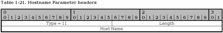
The Hostname parameter is used to send a single hostname as an address. Thea receiving host must then look up the hostname and use any and/or all of the addresses it receives from there. If a hostname parameter is sent, no other IPv4, IPv6 or Hostname parameters may be sent.
Type - bit 0-15. This is always set to 11 for Hostname Parameters.
Length - bit 16-31. The length of the whole parameter, including type, length and hostname field. The Hostname field is variable length. The length is counted in bytes.
Hostname - bit 32-n. A variable length parameter containing a hostname. The hostname is resolved by the receiving end to get the addresses that can be used to contact the sending endpoint.
SCTP INIT ACK chunk
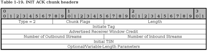
The INIT ACK chunk is sent in response to a INIT chunk and contains basically the same headers, but with values from the recipient of the original INIT chunk. In addition, it has two extra variable length parameters, the State Cookie and the Unrecognized Parameter parameters.
Type - bit 0-7. This header is always set to 2 for INIT ACK chunks.
Chunk flags - bit 8-15. Not used today. Might be applicable for change. See SCTP Common and generic headers for more information.
Chunk Length - bit 16-31. The chunk length is the length of the whole packet, including everything in the headers, and the optional parameters.
Initiate Tag - bit 32-63. The receiver of the Initiate Tag of the INIT ACK chunk must save this value and copy it into the Verification Tag field of every packet that it sends to the sender of the INIT ACK chunk. The Initiate Tag must not be 0, and if it is, the receiver of the INIT ACK chunk must close the connection with an ABORT.
Advertised Receiver Window Credit (a_rwnd) - bit 64-95. The dedicated buffers that the sender of this chunk has located for traffic, counted in bytes. The dedicated buffers should never be lowered to below this value.
Number of Outbound Streams - bit 96-111. How many outbound streams that the sending host wishes to create. Must not be 0, or the receiver of the INIT ACK should ABORT the association. There is no negotiation of the minimum number of outbound or inbound streams, it is simply set to the lowest that either host has set in the header.
Number of Inbound Streams - bit 112-127. How many inbound streams that the sending endpoint is willing to accept. Must not be 0, or the receiver of the INIT ACK should ABORT the association. There is no negotiation of the minimum number of outbound or inbound streams, it is simply set to the lowest that either host has set in the header.
Initial TSN - bit 128-159. This is set to the Initial Transmission Sequence Number (I-TSN) which will be used by the sending party in the association to start with.
After this point, the INIT ACK chunk continues with optional variable-length parameters. The parameters are exactly the same as for the INIT chunk, with the exception of the addition of the State Cookie and the Unrecognized Parameters parameter, and the deletion of the Supported Address Types parameter. The list in other words look like this:
Table 2-4. INIT ACK Variable Parameters
| Parameter Name | Status | Type Value |
|---|---|---|
| IPv4 Address | Optional | 5 |
| IPv6 Address | Optional | 6 |
| State Cookie | Mandatory | 7 |
| Unrecognized Parameters | Optional | 8 |
| Cookie Preservative | Optional | 9 |
| Host Name Address | Optional | 11 |
| Reserved for ECN Capable | Optional | 32768 |
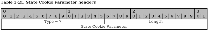
The State Cookie is used in INIT ACK to send a cookie to the other host, and until the receiving host has replied with a COOKIE ECHO chunk, the association is not guaranteed. This is to prevent basically the same as a SYN attack in TCP protocol.
Type - bit 0-15. Always set to 7 for all State Cookie parameters.
Length - bit 16-31. The size of the whole parameter, including the type, length and State Cookie field in bytes.
State Cookie - bit 31-n. This parameter contains a cookie of variable length. For a description on how this cookie is created, see the RFC 2960 - Stream Control Transmission Protocol document.
SCTP SACK chunk

The SACK chunk is used to tell the sender of DATA chunks which chunks has been received and where there has been a gap in the stream, based on the received TSN's. Basically, the SACK chunk acknowledges that it has received data up to a certain point (the Cumulative TSN Ack parameter), and then adds Gap Ack Blocks for all of the data that it has received after the Cumulative TSN Ack point. A SACK chunk must not be sent more than once for every DATA chunk that is received.
Type - bit 0-7. This header is always set to 3 for SACK chunks.
Chunk flags - bit 8-15. Not used today. Might be applicable for change. See SCTP Common and generic headers for more information.
Chunk Length - bit 16-31. The chunk length is the length of the whole chunk, including everything in the headers and all the parameters.
Cumulative TSN Ack - bit 32-63. This is the Cumulative TSN Ack parameter, which is used to acknowledge data. The DATA chunk receiver will use this field to tell the sending host that it has received all data up to this point of the association. After this point, all data that has not been specifically acknowledged by the Gap Ack Blocks will, basically, be considered unaccounted for.
Advertised Receiver Window Credit (a_rwnd) - bit 64-95. The a_rwnd field is basically the same as the a_rwnd in the INIT and INIT ACK chunks, but can be used to raise or lower the a_rwnd value. Please read more in the RFC 2960 - Stream Control Transmission Protocol document about this.
Number of Gap Ack Blocks - bit 96-111. The number of Gap Ack Blocks listed in this chunk. Each Gap Ack Block takes up 32 bits in the chunk.
Number of Duplicate TSNs - bit 112-127. The number of DATA chunks that has been duplicated. Each duplicated TSN is listed after the Gap Ack Blocks in the chunk, and each TSN takes 32 bits to send.
Gap Ack Block #1 Start - bit 128-143. This is the first Gap Ack Block in the SACK chunk. If there are no gaps in the received DATA chunk TSN numbers, there will be no Gap Ack Blocks at all. However, if DATA chunks are received out of order or some DATA chunks where lost during transit to the host, there will be gaps. The gaps that has been seen will be reported with Gap Ack Blocks. The Gap Ack Block start point is calculated by adding the Gap Ack Block Start parameter to the Cumulative TSN value. The calculated value is the start of the block.
Gap Ack Block #1 End - bit 144-159. This value reports the end of the first Gap Ack Block in the stream. All the DATA chunks with the TSN between the Gap Ack Block Start and the Gap Ack Block End has been received. The Gap Ack Block End value is added to the Cumulative TSN, just as the Start parameter, to get the actual last TSN of the block chunks to be Acknowledged.
Gap Ack Block #N Start - bits variable. For every Gap Ack Block counted in the Number of Gap Ack Blocks parameter, one Gap Ack Block is added, until the final N block. Ie, if Number of Gap Ack Blocks = 2, then there will be two Gap Ack Blocks in the SACK chunk. This is the last one simply, and contains the same type of value as the Gap Ack Block #1 Start.
Gap Ack Block #N End - bits variable. Same as for the Gap Ack Block #N End, but for the end of the gap.
Duplicate TSN #1 - bits variable. These fields report a duplicate TSN, in which case we have already received a specific chunk, but receive the same TSN several times more. This can either be router glitches (retransmitting already sent data) or a case of retransmission from the sending endpoint, or a score of other possibilities. Each instance of a duplicate TSN should be reported once. For example, if 2 duplicate TSN's has been received after acknowledging the first one, each of these duplicate TSN's should be sent sent in the next SACK message that is being sent. If even more duplicate TSN's should appear after this second SACK is sent, the new duplicates should be added in the next SACK, and so on.
Duplicate TSN #X - bits variable. This is the last duplicate TSN parameter, containing the same type of information as the first parameter.
SCTP SHUTDOWN chunk
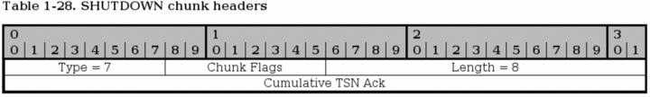
The SHUTDOWN chunk is issued when one of the endpoints of a connection wants to close the current association. The sending party must empty all of its sending buffers before sending the SHUTDOWN chunk, and must not send any more DATA chunks afterwards. The receiver must also empty its sending buffers and must then send the responding SHUTDOWN ACK chunk.
Type - bit 0-7. This header is always set to 7 for SHUTDOWN chunks.
Chunk flags - bit 8-15. Not used today. Might be applicable for change. See SCTP Common and generic headers for more information.
Chunk Length - bit 16-31. The chunk length is the length of the whole packet, including the Cumulative TSN Ack parameter. The length of the SHUTDOWN chunk should always be 8.
Cumulative TSN Ack - bit 32-63. This is a Cumulative TSN Ack field, just the same as in the SACK chunk. The Cumulative TSN Ack acknowledges the last TSN received in sequence from the opposite endpoint. This parameter does not, nor can the rest of the SHUTDOWN chunk either, acknowledge Gap Ack Blocks. The lack of a Gap Ack Block in the SHUTDOWN chunk that was acknowledged before should not be interpreted as if the previously acknowledged block was lost again.
SCTP SHUTDOWN ACK chunk

The SHUTDOWN ACK chunk is used to acknowledge a SHUTDOWN chunk that has been received. Before the SHUTDOWN ACK chunk is sent, all data in the sending buffers should be sent, but the buffers must not accept any new data from the application. SCTP does not support half-open connections as TCP does.
Type - bit 0-7. This header is always set to 8 for SHUTDOWN ACK chunks.
Chunk flags - bit 8-15. Not used today. Might be applicable for change. See SCTP Common and generic headers for more information.
Chunk Length - bit 16-31. The chunk length is the length of the whole chunk. The length of the SHUTDOWN ACK chunk should always be 4.
SCTP SHUTDOWN COMPLETE chunk

The SHUTDOWN COMPLETE chunk is sent, by the originating host of the SHUTDOWN, in response to the SHUTDOWN ACK chunk. It is sent to acknowledge that the association is finally closed.
Type - bit 0-7. Always set to 14 for SHUTDOWN COMPLETE chunks.
Reserved - bit 8-14. Not used today. Might be applicable for change. See SCTP Common and generic headers for more information.
T-bit - bit 15. The T-bit is not set to signal that the sending host had a Transmission Control Block (TCB) associated with this connection and that it destroyed. If the T-bit was set, it had no TCB to destroy.
Length - bit 16-31. This is always set to 4 for SHUTDOWN COMPLETE chunks, since the chunk should never be any larger, as long as no updates to the standards are made.
TCP/IP destination driven routing |
Page Up |
TCP/IP has grown in complexity quite a lot when it comes to the routing part. In the beginning, most people thought it would be enough with destination driven routing. The last few years, this has become more and more complex however. Today, Linux can route on basically every single field or bit in the IP header, and even based on TCP, UDP or ICMP headers as well. This is called policy based routing, or advanced routing.
This is simply a brief discussion on how the destination driven routing is performed. When we send a packet from a sending host, the packet is created. After this, the computer looks at the packet destination address and compares it to the routing table that it has. If the destination address is local, the packet is sent directly to that address via its hardware MAC address. If the packet is on the other side of a gateway, the packet is sent to the MAC address of the gateway. The gateway will then look at the IP headers and see the destination address of the packet. The destination address is looked up in the routing table again, and the packet is sent to the next gateway, et cetera, until the packet finally reaches the local network of the destination.
As you can see, this routing is very basic and simple. With the advanced routing and policy based routing, this gets quite a bit more complex. We can route packets differently based on their source address for example, or their TOS value, et cetera.
What's next? |
Page Up |
This chapter has brought you up to date to fully understand the subsequent chapters. The following has been gone through thoroughly:
-
TCP/IP structure
-
IP protocol functionality and headers.
-
TCP protocol functionality and headers.
-
UDP protocol functionality and headers.
-
ICMP protocol functionality and headers.
-
TCP/IP destination driven routing.
All of this will come in very handy later on when you start to work with the actual firewall rulesets. All of this information are pieces that fit together, and will lead to a better firewall design.
| Hosted by HB.BY | 2008 © iptables.info |