| Iptables |
| Home | Contents | Contact Us |
| Contents » Traversing of tables and chains | Printer friendly version |
|
Permission is granted to copy, distribute and/or modify this document under the terms of the GNU Free Documentation License, Version 1.1; with the Invariant Sections being "Introduction" and all sub-sections, with the Front-Cover Texts being "Original Author: Oskar Andreasson", and with no Back-Cover Texts. A copy of the license is included in the section entitled "GNU Free Documentation License". All scripts in this tutorial are covered by the GNU General Public License. The scripts are free source; you can redistribute them and/or modify them under the terms of the GNU General Public License as published by the Free Software Foundation, version 2 of the License. These scripts are distributed in the hope that they will be useful, but WITHOUT ANY WARRANTY; without even the implied warranty of MERCHANTABILITY or FITNESS FOR A PARTICULAR PURPOSE. See the GNU General Public License for more details. You should have received a copy of the GNU General Public License within this tutorial, under the section entitled "GNU General Public License"; if not, write to the Free Software Foundation, Inc., 59 Temple Place, Suite 330, Boston, MA 02111-1307 USA |
Chapter 6. Traversing of tables and chains
In this chapter we'll discuss how packets traverse the different chains, and in which order. We will also discuss the order in which the tables are traversed. We'll see how valuable this is later on, when we write our own specific rules. We will also look at the points which certain other components, that also are kernel dependent, enter into the picture. Which is to say the different routing decisions and so on. This is especially necessary if we want to write iptables rules that could change routing patterns/rules for packets; i.e. why and how the packets get routed, good examples of this are DNAT and SNAT. Not to be forgotten are, of course, the TOS bits.
General |
Page Up |
When a packet first enters the firewall, it hits the hardware and then gets passed on to the proper device driver in the kernel. Then the packet starts to go through a series of steps in the kernel, before it is either sent to the correct application (locally), or forwarded to another host - or whatever happens to it.
First, let us have a look at a packet that is destined for our own local host. It would pass through the following steps before actually being delivered to our application that receives it:
Table 6-1. Destination local host (our own machine)
| Step | Table | Chain | Comment |
|---|---|---|---|
| 1 | On the wire (e.g., Internet) | ||
| 2 | Comes in on the interface (e.g., eth0) | ||
| 3 | raw | PREROUTING | This chain is used to handle packets before the connection tracking takes place. It can be used to set a specific connection not to be handled by the connection tracking code for example. |
| 4 | This is when the connection tracking code takes place as discussed in the The state machine chapter. | ||
| 5 | mangle | PREROUTING | This chain is normally used for mangling packets, i.e., changing TOS and so on. |
| 6 | nat | PREROUTING | This chain is used for DNAT mainly. Avoid filtering in this chain since it will be bypassed in certain cases. |
| 7 | Routing decision, i.e., is the packet destined for our local host or to be forwarded and where. | ||
| 8 | mangle | INPUT | At this point, the mangle INPUT chain is hit. We use this chain to mangle packets, after they have been routed, but before they are actually sent to the process on the machine. |
| 9 | filter | INPUT | This is where we do filtering for all incoming traffic destined for our local host. Note that all incoming packets destined for this host pass through this chain, no matter what interface or in which direction they came from. |
| 10 |
Local process or application (i.e., server or client program). |
Note that this time the packet was passed through the INPUT chain instead of the FORWARD chain. Quite logical. Most probably the only thing that's really logical about the traversing of tables and chains in your eyes in the beginning, but if you continue to think about it, you'll find it will get clearer in time.
Now we look at the outgoing packets from our own local host and what steps they go through.
Table 6-2. Source local host (our own machine)
| Step | Table | Chain | Comment |
|---|---|---|---|
| 1 | Local process/application (i.e., server/client program) | ||
| 2 | Routing decision. What source address to use, what outgoing interface to use, and other necessary information that needs to be gathered. | ||
| 3 | raw | OUTPUT | This is where you do work before the connection tracking has taken place for locally generated packets. You can mark connections so that they will not be tracked for example. |
| 4 | This is where the connection tracking takes place for locally generated packets, for example state changes et cetera. This is discussed in more detail in the The state machine chapter. | ||
| 5 | mangle | OUTPUT | This is where we mangle packets, it is suggested that you do not filter in this chain since it can have side effects. |
| 6 | nat | OUTPUT | This chain can be used to NAT outgoing packets from the firewall itself. |
| 7 | Routing decision, since the previous mangle and nat changes may have changed how the packet should be routed. | ||
| 8 | filter | OUTPUT | This is where we filter packets going out from the local host. |
| 9 | mangle | POSTROUTING | The POSTROUTING chain in the mangle table is mainly used when we want to do mangling on packets before they leave our host, but after the actual routing decisions. This chain will be hit by both packets just traversing the firewall, as well as packets created by the firewall itself. |
| 10 | nat | POSTROUTING | This is where we do SNAT as described earlier. It is suggested that you don't do filtering here since it can have side effects, and certain packets might slip through even though you set a default policy of DROP. |
| 11 | Goes out on some interface (e.g., eth0) | ||
| 12 | On the wire (e.g., Internet) |
In this example, we're assuming that the packet is destined for another host on another network. The packet goes through the different steps in the following fashion:
Table 6-3. Forwarded packets
| Step | Table | Chain | Comment |
|---|---|---|---|
| 1 | On the wire (i.e., Internet) | ||
| 2 | Comes in on the interface (i.e., eth0) | ||
| 3 | raw | PREROUTING | Here you can set a connection to not be handled by the connection tracking system. |
| 4 | This is where the non-locally generated connection tracking takes place, and is also discussed more in detail in the The state machine chapter. | ||
| 5 | mangle | PREROUTING | This chain is normally used for mangling packets, i.e., changing TOS and so on. |
| 6 | nat | PREROUTING | This chain is used for DNAT mainly. SNAT is done further on. Avoid filtering in this chain since it will be bypassed in certain cases. |
| 7 | Routing decision, i.e., is the packet destined for our local host or to be forwarded and where. | ||
| 8 | mangle | FORWARD | The packet is then sent on to the FORWARD chain of the mangle table. This can be used for very specific needs, where we want to mangle the packets after the initial routing decision, but before the last routing decision made just before the packet is sent out. |
| 9 | filter | FORWARD | The packet gets routed onto the FORWARD chain. Only forwarded packets go through here, and here we do all the filtering. Note that all traffic that's forwarded goes through here (not only in one direction), so you need to think about it when writing your rule-set. |
| 10 | mangle | POSTROUTING | This chain is used for specific types of packet mangling that we wish to take place after all kinds of routing decisions have been done, but still on this machine. |
| 11 | nat | POSTROUTING | This chain should first and foremost be used for SNAT. Avoid doing filtering here, since certain packets might pass this chain without ever hitting it. This is also where Masquerading is done. |
| 12 | Goes out on the outgoing interface (i.e., eth1). | ||
| 13 | Out on the wire again (i.e., LAN). |
As you can see, there are quite a lot of steps to pass through. The packet can be stopped at any of the iptables chains, or anywhere else if it is malformed; however, we are mainly interested in the iptables aspect of this lot. Do note that there are no specific chains or tables for different interfaces or anything like that. FORWARD is always passed by all packets that are forwarded over this firewall/router.
 |
Do not use the INPUT chain to filter on in the previous scenario! INPUT is meant solely for packets to our local host that do not get routed to any other destination. |
We have now seen how the different chains are traversed in three separate scenarios. If we were to figure out a good map of all this, it would look something like this:
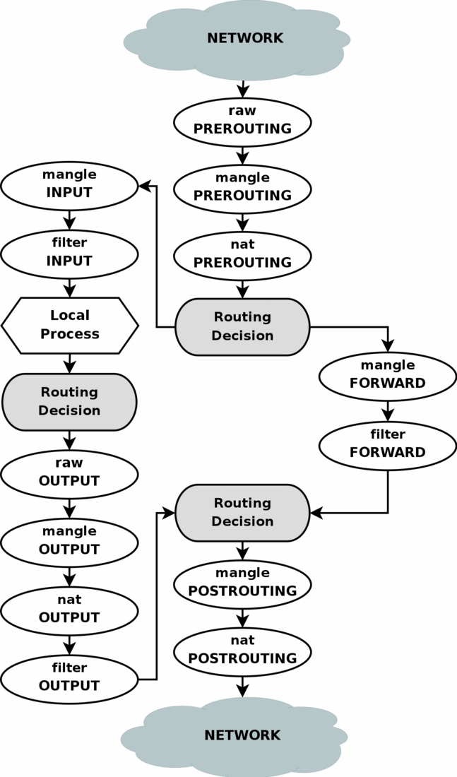
To clarify this image, consider this. If we get a packet into the first routing decision that is not destined for the local machine itself, it will be routed through the FORWARD chain. If the packet is, on the other hand, destined for an IP address that the local machine is listening to, we would send the packet through the INPUT chain and to the local machine.
Also worth a note, is the fact that packets may be destined for the local machine, but the destination address may be changed within the PREROUTING chain by doing NAT. Since this takes place before the first routing decision, the packet will be looked upon after this change. Because of this, the routing may be changed before the routing decision is done. Do note, that all packets will be going through one or the other path in this image. If you DNAT a packet back to the same network that it came from, it will still travel through the rest of the chains until it is back out on the network.
 |
If you feel that you want more information, you could use the rc.test-iptables.txt script. This test script should give you the necessary rules to test how the tables and chains are traversed. |
Mangle table |
Page Up |
This table should as we've already noted mainly be used for mangling packets. In other words, you may freely use the mangle targets within this table, to change TOS (Type Of Service) fields and the like.
|
You are strongly advised not to use this table for any filtering; nor will any DNAT, SNAT or Masquerading work in this table. |
The following targets are only valid in the mangle table. They can not be used outside the mangle table.
-
TOS
-
TTL
-
MARK
-
SECMARK
-
CONNSECMARK
The TOS target is used to set and/or change the Type of Service field in the packet. This could be used for setting up policies on the network regarding how a packet should be routed and so on. Note that this has not been perfected and is not really implemented on the Internet and most of the routers don't care about the value in this field, and sometimes, they act faulty on what they get. Don't set this in other words for packets going to the Internet unless you want to make routing decisions on it, with iproute2.
The TTL target is used to change the TTL (Time To Live) field of the packet. We could tell packets to only have a specific TTL and so on. One good reason for this could be that we don't want to give ourself away to nosy Internet Service Providers. Some Internet Service Providers do not like users running multiple computers on one single connection, and there are some Internet Service Providers known to look for a single host generating different TTL values, and take this as one of many signs of multiple computers connected to a single connection.
The MARK target is used to set special mark values to the packet. These marks could then be recognized by the iproute2 programs to do different routing on the packet depending on what mark they have, or if they don't have any. We could also do bandwidth limiting and Class Based Queuing based on these marks.
The SECMARK target can be used to set security context marks on single packets for usage in SELinux and other security systems that are able to handle these marks. This is then used for very fine grained security on what subsystems of the system can touch what packets et cetera. The SECMARK can also be set on a whole connection with the CONNSECMARK target.
CONNSECMARK is used to copy a security context to or from a single packet from or to the whole connection. This is then used by the SELinux and other security systems to do more fine-grained security on a connection level.
Nat table |
Page Up |
This table should only be used for NAT (Network Address Translation) on different packets. In other words, it should only be used to translate the packet's source field or destination field. Note that, as we have said before, only the first packet in a stream will hit this table. After this, the rest of the packets will automatically have the same action taken on them as the first packet. The actual targets that do these kind of things are:
-
DNAT
-
SNAT
-
MASQUERADE
-
REDIRECT
The DNAT target is mainly used in cases where you have a public IP and want to redirect accesses to the firewall to some other host (on a DMZ for example). In other words, we change the destination address of the packet and reroute it to the host.
SNAT is mainly used for changing the source address of packets. For the most part you'll hide your local networks or DMZ, etc. A very good example would be that of a firewall of which we know outside IP address, but need to substitute our local network's IP numbers with that of our firewall. With this target the firewall will automatically SNAT and De-SNAT the packets, hence making it possible to make connections from the LAN to the Internet. If your network uses 192.168.0.0/netmask for example, the packets would never get back from the Internet, because IANA has regulated these networks (among others) as private and only for use in isolated LANs.
The MASQUERADE target is used in exactly the same way as SNAT, but the MASQUERADE target takes a little bit more overhead to compute. The reason for this, is that each time that the MASQUERADE target gets hit by a packet, it automatically checks for the IP address to use, instead of doing as the SNAT target does - just using the single configured IP address. The MASQUERADE target makes it possible to work properly with Dynamic DHCP IP addresses that your ISP might provide for your PPP, PPPoE or SLIP connections to the Internet.
Raw table |
Page Up |
The raw table is mainly only used for one thing, and that is to set a mark on packets that they should not be handled by the connection tracking system. This is done by using the NOTRACK target on the packet. If a connection is hit with the NOTRACK target, then conntrack will simply not track the connection. This has been impossible to solve without adding a new table, since none of the other tables are called until after conntrack has actually been run on the packets, and been added to the conntrack tables, or matched against an already available connection. You can read more about this in the The state machine chapter.
This table only has the PREROUTING and OUTPUT chains. No other chains are required since these are the only places that you can deal with packets before they actually hit the connection tracking.
 |
For this table to work, the iptable_raw module must be loaded. It will be loaded automatically if iptables is run with the -t raw keywords, and if the module is available. |
|
The raw table is a relatively new addition to iptables and the kernel. It might not be available in early 2.6 and 2.4 kernels unless patched. |
Filter table |
Page Up |
The filter table is mainly used for filtering packets. We can match packets and filter them in whatever way we want. This is the place that we actually take action against packets and look at what they contain and DROP or /ACCEPT them, depending on their content. Of course we may also do prior filtering; however, this particular table is the place for which filtering was designed. Almost all targets are usable in this table. We will be more prolific about the filter table here; however you now know that this table is the right place to do your main filtering.
User specified chains |
Page Up |
If a packet enters a chain such as the INPUT chain in the filter table, we can specify a jump rule to a different chain within the same table. The new chain must be userspecified, it may not be a built-in chain such as the INPUT or FORWARD chain for example. If we consider a pointer pointing at the rule in the chain to execute, the pointer will go down from rule to rule, from top to bottom until the chain traversal is either ended by a target or the main chain (I.e., FORWARD, INPUT, et cetera) ends. Once this happens, the default policy of the built-in chain will be applied.
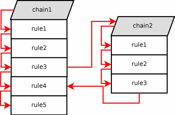
If one of the rules that matches points to another userspecified chain in the jump specification, the pointer will jump over to this chain and then start traversing that chain from the top to bottom. For example, see how the rule execution jumps from rule number 3 to chain 2 in the above image. The packet matched the matches contained in rule 3, and the jump/target specification was set to send the packet on for further examination in chain 2.
|
Userspecified chains can not have a default policy at the end of the chain. Only built in chains can have this. This can be circumvented by appending a single rule at the end of the chain that has no matches, and hence it will behave as a default policy. If no rule is matched in a userspecified chain, the default behaviour is to jump back to the originating chain. As seen in the image above, the rule execution jumps from chain 2 and back to chain 1 rule 4, below the rule that sent the rule execution into chain 2 to begin with. |
Each and every rule in the user specified chain is traversed until either one of the rules matches -- then the target specifies if the traversing should end or continue -- or the end of the chain is reached. If the end of the user specified chain is reached, the packet is sent back to the invoking chain. The invoking chain can be either a user specified chain or a built-in chain.
What's next? |
Page Up |
In this chapter we have discussed several of the chains and tables and how they are traversed, including the standard built-in chains and userspecified chains. This is a very important area to understand. It may be simple, but unless fully understood, fatal mistakes can be equally easily.
The next chapter will deal in depth with the state machine of netfilter, and how states are traversed and set on packets in a connection tracking machine. The next chapter is in other words just as important as this chapter has been.
| Hosted by HB.BY | 2008 © iptables.info |